
- Cortex M1 и Cortex M3 в открытом доступе.
- Zynq-7000 SoC — Xilinx. Z-turn Lite. Bare metal. Часть 1.
- Zynq-7000 SoC — Xilinx. Z-turn Lite. Bare metal. Часть 2.
Cortex-M1
Некоторое время назад, мной был сделан обзор о доступности Cortex M1 и M3, по первой ссылке Вы сможете возобновить знания об этих ядрах. В этой статье я хотел бы поделиться знанием о том, как запустить ядро Cortex M1 на отличной платформе, например на zynq. Вторая и третья ссылка позволит быстро войти в курс проектирования под zynq и даст базовое понимание о работе в Vivado.
Ядро Cortex-M1 – оптимизировано для использования на FPGA. Cortex-M1 ориентирован на OEM-производителей, которые смогут унифицировать и специализировать архитектуру своих решений. ARM Cortex-M1 представляет собой 32-разрядный RISC-процессор с трехступенчатым конвейером, использующим несколько модифицированный набор инструкций Thumb-2. Процессорное ядро, как утверждается, способно исполнять код Thumb, таким образом, программно совместимо с ARM7TDMI и старше. Cortex-M1 может работать на частотах более 170 МГц, обеспечивая производительность 0,8 DMIPS (млн. инструкций в секунду)/МГц. Основными приложениями для Cortex-M1 являются встроенные средства управления, коммуникации, промышленное оборудование, сетевое оборудование и устройства авиации.
Xilinx Vivado
1. Создаём новый проект в Xilinx Vivado, называем проект “Cortex M1”.

2. Выбираем необходимый камень.

3. Добавляем директорию с IP ARM Cortex M1.

4. Видим, что в добавленной директории находится необходимое нам IP.

5. Добавляем ip Zynq и ip Cortex M1.

6. Добавленное ядро Cortex M1 в блок дизайне.

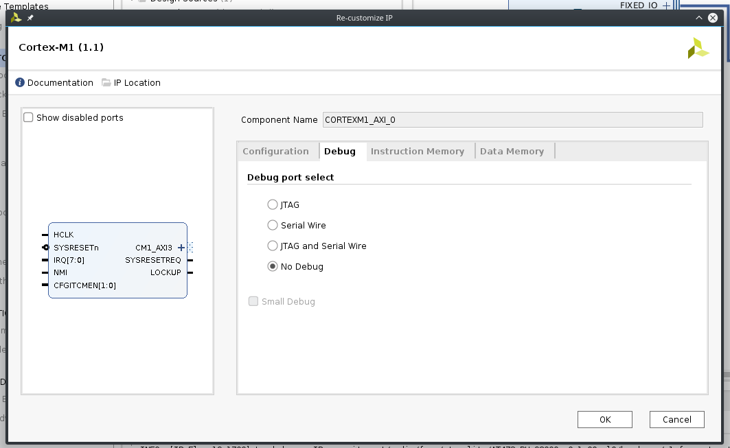
7. Конфигурируем Cortex M1, в ядре убираем отладку, ставим режим без отладчика, чтобы сэкономить пространство pl части Zynq.
8. Добавляем IP axi uartlite, данное ядро было использовано в предыдущей статье.

9. Устанавливаем скорость в 115200 для IP axi uartlite.

10. Добавляем IP AXI GPIO, для AXI GPIO делаем настройку, как на скриншоте ниже.

11. Добавляем IP констант для Cortex M1. Константа значение 0 для порта прерываний, константа значение 0 для порта NVIC, константа значение 3 для порта CFGITCMEM, далее делаем автоматическое соединение линий и шин в Vivado для нашего проекта, итоговый проект должен иметь вид как на скриншоте.

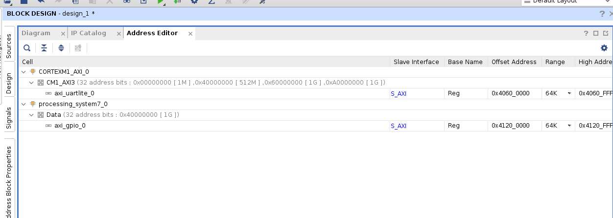
12. Проверяем адресное пространство, если адресное пространство не назначено для IP, необходимо сделать назначение.
13. Запускаем синтез проекта, после синтеза проекта настраиваем порты io для axi uartlite, в меню портов, красным цветом подсвечены порты которые не определены.

14. Порты axi uartlite назначим на io_b35_ln3 и io_b35_ln2.

15. Данный банк запитан от 3.3В, напряжение для банка выбирается с помощью джампера на основной плате с zynq.

16. Порты io_b35_ln3 и io_b35_ln2 на разъеме J4.

17. Порты io_b35_ln3 и io_b35_ln2 на камне. Далее создаем файл ограничения целостности сигнала, и в него либо руками вводим содержание под скриншотом, либо назначаем порты через меню.

Содержание файла XDC.
set_property IOSTANDARD LVCMOS33 [get_ports uart_rtl_0_rxd]
set_property IOSTANDARD LVCMOS33 [get_ports uart_rtl_0_txd]
set_property PACKAGE_PIN D18 [get_ports uart_rtl_0_rxd]
set_property PACKAGE_PIN A20 [get_ports uart_rtl_0_txd]
18. Выполняем имплементацию проекта. Результат имплементации проекта.

После имплементации проекта необходимо выполнить файл make_mmi_file.tcl, source make_mmi_file.tcl, содержание файла ниже.
# -----------------------------------------------------------------------------
#  The confidential and proprietary information contained in this file may
#  only be used by a person authorised under and to the extent permitted
#  by a subsisting licensing agreement from ARM limited.
#
#             (C) COPYRIGHT 2018 ARM limited.
#                 ALL RIGHTS RESERVED
#
#  This entire notice must be reproduced on all copies of this file
#  and copies of this file may only be made by a person if such person is
#  permitted to do so under the terms of a subsisting license agreement
#  from ARM limited.
#
#       SVN Information
#
#       Checked In          : $Date$
#
#       Revision            : $Revision$
#
#       Release Information : Cortex-M1 DesignStart-r0p1-00rel0
#
# -----------------------------------------------------------------------------
#  Project : Cortex-M1 Arty A7 Example design with V2C-DAPLink adaptor board
#
#  Purpose : Script to get ITCM BRAM locations
#            MMI format from following two articles
#
# https://www.xilinx.com/support/answers/63041.html
# https://forums.xilinx.com/t5/Vivado-TCL-Community/export-BRAM-locations-into-MMI-file/td-p/771221
# -----------------------------------------------------------------------------

# Set MMI output file name
set mmi_file "m1.mmi"
set part     "xc7z010clg400-1"

# Function to swap bits
proc swap_bits { bit } {

    if { $bit > 23 } {return [expr {24 + (31 - $bit)}]}
    if { $bit > 15 } {return [expr {16 + (23 - $bit)}]}
    if { $bit > 7  } {return [expr {8  + (15 - $bit)}]}
    return [expr {7 - $bit}]
}

# Find all the ITCM RAMs, place in a list
set itcm_ram [get_cells -hier -regexp {.*itcm.*ram_block_reg.*} -filter {REF_NAME =~ RAMB36E1}]

# Vivado appears to read the memories in their actual bit order
# However update_mem amongst its very many failings doesn't support endianness, even though you specify it in the file!
# It also pays no attention to the bit_lane definition, it does the conversion based on the order memories are defined
# in the file!  Not clear what the MMI file does achieve!

# So go through and reverse each block of 4 memories
if { [expr {[llength $itcm_ram] % 4}] != 0 } {
    puts "Error - Number of memories not divisible by 4"
    return -1
}

# Number of RAMs details memory size.  Each RAM is 32kb, so 4kB.
set itcm_size_bytes [expr {4096*[llength $itcm_ram]}]
puts "Instruction memory size $itcm_size_bytes"

# Currently only support memory sizes between 16kB, (one byte per mem), and 128kB, (one bit per mem)
if { ($itcm_size_bytes <= (4*4096)) || ($itcm_size_bytes > (32*4096)) } {
    puts "Error - Memory size of $itcm_size_bytes out of range"
    puts "        Script only supports memory sizes between 16kB and 128kB"
    return -1
}

# Create and open target mmi file
set fp [open $mmi_file {WRONLY CREAT TRUNC}]
if { $fp == 0 } {
    puts "Error - Unable to open $mmi_file for writing"
    return -1
}

# Write the file header
puts $fp "<?xml version=\"1.0\" encoding=\"UTF-8\"?>"
puts $fp "<MemInfo Version=\"1\" Minor=\"15\">"
puts $fp "    <Processor Endianness=\"ignored\" InstPath=\"dummy\">"
puts $fp "        <AddressSpace Name=\"design_1_i.CORTEXM1_AXI_0.inst.u_x_itcm\" Begin=\"0\" End=\"[expr {$itcm_size_bytes-1}]\">"
puts $fp "            <BusBlock>"

# Create an array to put the location and top memory index into
array set mem_array {}

# Calculate the expected number of bits per memory
set mem_bits [expr {32/[llength $itcm_ram]}]

# set itcm_ram_reordered [list]

for {set i 0} {$i < [llength $itcm_ram]/4} {incr i} {
    set start     [expr {$i*4}]
    set end       [expr {($i*4)+3}]
    set new_list  [lreverse [lrange $itcm_ram [expr {$i*4}] [expr {($i*4)+3}]]]
#    puts "$start $end\n$new_list"
    # lreplace $itcm_ram [expr {$i*4}] [expr {($i*4)+3}] [lreverse [lrange $itcm_ram [expr {$i*4}] [expr {($i*4)+3}]]]


# puts $itcm_ram_reordered

    # For each entry display the location
    foreach ram $new_list {
        # Get the RAM location
        set loc_val [get_property LOC [get_cells $ram]]
        regexp -- {(RAMB36_)([0-9XY]+)} $loc_val full ram_name loc_xy

        # Get the nets driven by the D0 pins
        set data_bus [get_nets -of_objects [get_pins -filter {REF_PIN_NAME =~ DOADO*} -of [get_cells $ram]]]

        # Check number of bits is the same as that expected
        if { [llength $data_bus] != $mem_bits } {
            puts "Error - Number of data pins read, [llength $data_bus], does not equal expected memory bits, $mem_bits"
            return -1
        }

        # Number of pins connected to the memory sets the memory depth.
        set memory_depth [expr {(32768/[llength $data_bus])-1}]

        set idx_list [list]
        foreach entry $data_bus {
            # Filter the data_bus down to just the two index numbers
            set index [regexp -inline -- {[0-9]+} [regexp -inline -- {\[.*} [lindex $entry 0]]]
            lappend idx_list $index
        }

        # Sort the index list from highest to lowest
        set idx_list [lsort -decreasing -integer $idx_list]

        # Assign the highest and lowest bits for the range variables
        set index_low  [lindex $idx_list end]
        set index_high [lindex $idx_list 0]

        # Debug
        # puts $data_bus
        # puts $idx_list
        # puts "$index_high downto $index_low pos $loc_val"

        array set mem_array [list $index_high $loc_xy]
    }; # foreach
}; # for

    # Sort array into index order
    array set mem_array_sorted {}

    foreach entry [lsort [array names mem_array]] {
        array set mem_array_sorted [list $entry $mem_array($entry)]
    }

    foreach entry [array names mem_array_sorted] {
        # puts "$entry : $mem_array_sorted($entry)"
    }

    # MMI file needs to be in little endian format because update_mem doesn't actually use the endianness field
    # So first index is 7, next is 15, 23, 31.
    # Number of entries to write is 8/mem_bits.  Lower index is index_high - (mem_bits - 1)
    for {set top_idx 7} {$top_idx < 32} {incr top_idx 8} {
        for {set idx_high $top_idx} {$idx_high > ($top_idx-8)} {incr idx_high -$mem_bits} {
            # puts $idx_high
            set loc $mem_array_sorted($idx_high)
            set idx_low [expr {$idx_high - $mem_bits + 1}]

            if { $loc == "" } {
                puts "Error - No location entry for index $idx_high"
                return -1
            }

            # Write relevant XML
            puts $fp "                <BitLane MemType=\"RAMB36\" Placement=\"$loc\">"
            puts $fp "                    <DataWidth MSB=\"$idx_high\" LSB=\"$idx_low\"/>"
            puts $fp "                    <AddressRange Begin=\"0\" End=\"$memory_depth\"/>"
            puts $fp "                    <Parity ON=\"false\" NumBits=\"0\"/>"
            puts $fp "                </BitLane>"
        }
    }


# Write the file tail
puts $fp "            </BusBlock>"
puts $fp "        </AddressSpace>"
puts $fp "    </Processor>"
puts $fp "    <Config>"
puts $fp "        <Option Name=\"Part\" Val=\"$part\"/>"
puts $fp "    </Config>"
puts $fp "    <DRC>"
puts $fp "      <Rule Name=\"RDADDRCHANGE\" Val=\"false\"/>"
puts $fp "    </DRC>"
puts $fp "</MemInfo>"

# Close the output file
close $fp


# Useful facilities
# Get the bus as a list
# get_nets -hierarchical -regexp  {.*itcm.*doutA.*}
Данный файл создаст “m1.mmi” файл, который содержит описание адресного пространства Cortex-M1.
Файл m1.mmi
<?xml version="1.0" encoding="UTF-8"?>
<MemInfo Version="1" Minor="15">
    <Processor Endianness="ignored" InstPath="dummy">
        <AddressSpace Name="design_1_i.Cortex_M1_0.inst.u_x_itcm" Begin="0" End="32767">
            <BusBlock>
                <BitLane MemType="RAMB36" Placement="X1Y1">
                    <DataWidth MSB="7" LSB="4"/>
                    <AddressRange Begin="0" End="8191"/>
                    <Parity ON="false" NumBits="0"/>
                </BitLane>
                <BitLane MemType="RAMB36" Placement="X0Y1">
                    <DataWidth MSB="3" LSB="0"/>
                    <AddressRange Begin="0" End="8191"/>
                    <Parity ON="false" NumBits="0"/>
                </BitLane>
                <BitLane MemType="RAMB36" Placement="X2Y2">
                    <DataWidth MSB="15" LSB="12"/>
                    <AddressRange Begin="0" End="8191"/>
                    <Parity ON="false" NumBits="0"/>
                </BitLane>
                <BitLane MemType="RAMB36" Placement="X1Y0">
                    <DataWidth MSB="11" LSB="8"/>
                    <AddressRange Begin="0" End="8191"/>
                    <Parity ON="false" NumBits="0"/>
                </BitLane>
                <BitLane MemType="RAMB36" Placement="X0Y6">
                    <DataWidth MSB="23" LSB="20"/>
                    <AddressRange Begin="0" End="8191"/>
                    <Parity ON="false" NumBits="0"/>
                </BitLane>
                <BitLane MemType="RAMB36" Placement="X1Y3">
                    <DataWidth MSB="19" LSB="16"/>
                    <AddressRange Begin="0" End="8191"/>
                    <Parity ON="false" NumBits="0"/>
                </BitLane>
                <BitLane MemType="RAMB36" Placement="X1Y4">
                    <DataWidth MSB="31" LSB="28"/>
                    <AddressRange Begin="0" End="8191"/>
                    <Parity ON="false" NumBits="0"/>
                </BitLane>
                <BitLane MemType="RAMB36" Placement="X0Y5">
                    <DataWidth MSB="27" LSB="24"/>
                    <AddressRange Begin="0" End="8191"/>
                    <Parity ON="false" NumBits="0"/>
                </BitLane>
            </BusBlock>
        </AddressSpace>
    </Processor>
    <Config>
        <Option Name="Part" Val="xc7z010clg400-1"/>
    </Config>
    <DRC>
      <Rule Name="RDADDRCHANGE" Val="false"/>
    </DRC>
19. Результат выполнения команды source make_mmi_file.tcl.

20. Генерируем bitstream.

21. Итоговый результат утилизации ресурсов pl части Zynq, информация об утилизации ресурсов в виде графика.

22. Информация об утилизации ресурсов в виде таблицы.

Xilinx SDK
23. Запускаем SDK (предварительно сделав экспорт проекта), в настройках добавляем глобальную директорию, как на скриншоте ниже.

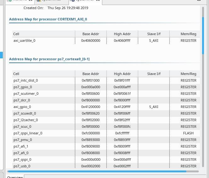
24. Адресное пространство проекта в SDK.
25. Создаем BSP для Cortex M1.

26. Настраиваем bsp, самое главное – это проверить чтобы стандартный поток шел через axi uartlite.

27. Запускаем проект в Keil для генерации elf файла. Путь до проекта software/m1_for_arty_s7/Build_Keil. В sdk_workspace добавляем сгенерируемый bsp, а также файлы Xpsuedo_asm_rvct.c и Xpseudo_asm_rvct.h, путь до файлов vivado/Arm_sw_repository/CortexM/bsp/standalone_v6_7/src/arm/cortexm1/armcc. Все исходники на которые будет ругаться Keil будем удалять.

Исходный код проекта для Keil.
/*
 * Copyright:
 * ----------------------------------------------------------------
 * This confidential and proprietary software may be used only as
 * authorised by a licensing agreement from ARM Limited
 *   (C) COPYRIGHT 2014, 2016 ARM Limited
 *       ALL RIGHTS RESERVED
 * The entire notice above must be reproduced on all authorised
 * copies and copies may only be made to the extent permitted
 * by a licensing agreement from ARM Limited.
 * ----------------------------------------------------------------
 * File:     main.c
 * Release Information : Cortex-M1 DesignStart-r0p1-00rel0
 * ----------------------------------------------------------------
 *
 */

/*
 * --------Included Headers--------
 */

#include <stdio.h>
#include <ctype.h>
#include <string.h>
#include <stdlib.h>
#include <time.h>

// Xilinx specific headers
#include "xparameters.h"
//#include "xgpio.h"

#include "m1_for_arty.h"        // Project specific header
#include "gpio.h"
#include "uart.h"
#include "spi.h"

/*******************************************************************/

int main (void)
{

    // Define local variables
    int     status;
    int     DAPLinkFittedn;
    int     i;
    int     readbackError;
    char    debugStr[256];

    // Illegal location
    volatile u32 emptyLoc;

    // CPU ID register
    volatile u32 *pCPUId = (u32 *)0xE000ED00;
    volatile u32 CPUId;
    int          CPU_part;
    int          CPU_rev;
    int          CPU_var;
    char         CPU_name[20];

    // init_platform is defined in platform.c
    // It calls enable_caches which is uBlaze specific and then init_uart
    InitialiseUART();

    // Clear all interrupts
    NVIC_ClearAllPendingIRQ();

    // Enable the UART interrupt
    NVIC_EnableIRQ(UART0_IRQn);

    // Enable UART Interrupts
    EnableUARTInterrupts();

    // Read the DAPLinkFitted input, (assigned to IRQ[31]).
    // Note the IRQ is never enabled, so polling the pending register will indicate the status
    NVIC_DisableIRQ(DAPLinkFittedn_IRQn);
    DAPLinkFittedn = NVIC_GetPendingIRQ( DAPLinkFittedn_IRQn );

    // Set DAPLink QSPI to the normal read-write controller
    // Do NOT do this for code running from the DAPLink QSPI.  This will switch from the XIP QSPI
    // controller to the standard controller, so the processor will not be able to access it's code image
    // This should only be done if the XIP QSPI is used to copy code to internal TCM, then boot-load from that TCM
    // SetDAPLinkQSPIMode( QSPI_QSPIMODE );

    // Read the CPU ID register to auto-detect the CPU and revision
    // Note however that code is compiled for a specific processor, so even though
    // the processor can be auto-detected, if the compiled code has extended commands not
    // supported by the processor, then runtime issues can occur
    CPUId    = *pCPUId;
    CPU_var  = ((CPUId & 0x00F00000) >> 20);
    CPU_part = ((CPUId & 0x0000FFF0) >> 4);
    CPU_rev  = CPUId & (0x0000000F);

    switch (CPU_part)
    {
        case 0xC21 : strcpy(  CPU_name, "Cortex-M1" ); break;
        case 0xC23 : strcpy(  CPU_name, "Cortex-M3" ); break;
        default    : sprintf( CPU_name, "Unknown %x", CPU_part );
    }

    sprintf (debugStr, "Arm %s Revision %i Variant %i\r\n\n", CPU_name, CPU_rev, CPU_var );

#ifndef SIM_BUILD
    // Use Xilinx version print command
    print ("************************************\r\n");
    print ( debugStr );
    print ("Example design for Digilent S7 board\r\n");
    if ( DAPLinkFittedn )
        print ("\nV2C-DAPLink board not detected\r\n");
    else
        print ("\nV2C-DAPLink board detected\r\n");
    print ("Use DIP switches and push buttons to\r\ncontrol LEDS\r\n");
    print ("Version 1.2\r\n");
    print ("************************************\r\n");
#else
    print ( debugStr );
#endif


    // Main loop.  Handle LEDs and switches via interrupt
    while ( 1 )
    {
        /* Main loop. Wait for interrupts to occur */
        /*
        if ( CheckUARTRxBytes() != 0 )
            print ("x");
        */
				print("mcu.by");
    }
}

/* Interrupt handler for DAPLink Fitted */
// This routine should never be called as the signal is used as IO
// Routine created to prevent exceptions in the case the IRQ is enabled
void DAPLinkFittedn ( void )
{
    // Clear the IRQ and disable any future IRQs
    NVIC_ClearPendingIRQ(DAPLinkFittedn_IRQn);
    NVIC_DisableIRQ(DAPLinkFittedn_IRQn);
}
Исходный код bat файла для генерации elf, тут самое главное правильный путь до fromelf, с помощью fromelf генерируется elf файл.
@REM -----------------------------------------------------------------------------
@REM  The confidential and proprietary information contained in this file may
@REM  only be used by a person authorised under and to the extent permitted
@REM  by a subsisting licensing agreement from ARM limited.
@REM
@REM             (C) COPYRIGHT 2018 ARM limited.
@REM                 ALL RIGHTS RESERVED
@REM
@REM  This entire notice must be reproduced on all copies of this file
@REM  and copies of this file may only be made by a person if such person is
@REM  permitted to do so under the terms of a subsisting license agreement
@REM  from ARM limited.
@REM
@REM       SVN Information
@REM
@REM       Checked In          : $Date$
@REM
@REM       Revision            : $Revision$
@REM
@REM       Release Information : Cortex-M1 DesignStart-r0p1-00rel0
@REM
@REM -----------------------------------------------------------------------------
@REM  Project : Cortex-M1 Arty A7 Example design with V2C-DAPLink adaptor board
@REM
@REM  Purpose : Convert axf file to hex for both BRAM and QSPI simulation models
@REM            Also convert axf file to elf for bitstream generation
@REM -----------------------------------------------------------------------------

@REM - Create the output files.
@REM - File to load into FPGA RAM
call C:\Keil_v5\ARM\ARMCC\bin\fromelf --vhx --32x1 --output bram_s7.hex objects\m1_for_arty_s7.axf
@REM - File to merge SW into bitstream
call C:\Keil_v5\ARM\ARMCC\bin\fromelf --elf        --output bram_s7.elf objects\m1_for_arty_s7.axf
@REM - File to load into DAPLink QSPI simulation
call C:\Keil_v5\ARM\ARMCC\bin\fromelf --vhx --8x1  --output qspi_s7.hex objects\m1_for_arty_s7.axf
@REM - Files to load onto DAPLink QSPI board
call C:\Keil_v5\ARM\ARMCC\bin\fromelf --bin        --output qspi_s7.bin objects\m1_for_arty_s7.axf

@REM - Copy the files to the relevant directories of the hardware project
copy bram_s7.* ..\..\..\hardware\m1_for_arty_s7\m1_for_arty_s7
copy qspi_s7.hex ..\..\..\hardware\m1_for_arty_s7\testbench
Все итоговые части проекта готовы для запуска на железе, переносим файл design_1_wrapper.bit, bram_s7.elf и m1.mmi в одну директорию и выполняем source make_prog_files.tcl. И получаем файл zynq_m1.bit, который содержит уже все необходимое.
Содержание файла make_prog_files.tcl.
# -----------------------------------------------------------------------------
#  The confidential and proprietary information contained in this file may
#  only be used by a person authorised under and to the extent permitted
#  by a subsisting licensing agreement from ARM limited.
#
#             (C) COPYRIGHT 2018 ARM limited.
#                 ALL RIGHTS RESERVED
#
#  This entire notice must be reproduced on all copies of this file
#  and copies of this file may only be made by a person if such person is
#  permitted to do so under the terms of a subsisting license agreement
#  from ARM limited.
#
#       SVN Information
#
#       Checked In          : $Date$
#
#       Revision            : $Revision$
#
#       Release Information : Cortex-M1 DesignStart-r0p1-00rel0
#
# -----------------------------------------------------------------------------
#  Project : Cortex-M1 Arty A7 Example design with V2C-DAPLink adaptor board
#
#  Purpose : Script to create bit and mcs files for Arty A7 board
#
#            Combines the original bit file, mmi file, and software elf to create
#            the full bitstream
#            Then converts full bitstream to mcs for download to the onboard flash
#
#            Can be run either in Vivado GUI TCL console, or else in batch mode
#            from command line
#            If run in Vivado TCL console, pwd needs to be set to root of project,
#            in the same location as the bit file
# -----------------------------------------------------------------------------

# Input files
set mmi_file            "./m1.mmi"
set elf_file            "./bram_s7.elf"
set source_bit_file     "./design_1_wrapper.bit"
#set reference_bit_file  "./m1_for_arty_s7_reference.bit"

# Output files
set output_bit_file "zynq_m1.bit"
set output_mcs_file "zynq_m1.mcs"

# Enable to turn on debug
set updatemem_debug 0

# Assemble bit file that can be downloaded to device directly
# Combine the original bit file, mmi file, and software elf to create the full bitstream

# Delete target file
file delete -force $output_bit_file
file delete -force $output_mcs_file

# Determine if the user has built the project and has the target source file
# If not, then use the reference bit file shipped with the project
if { ![file exists $source_bit_file] } {
    puts "\n********************************************"
    puts "INFO - File $source_bit_file doesn't exist as project has not been built"
    puts "       Using $reference_bit_file instead\n"
    puts "********************************************/n"
    set source_bit_file $reference_bit_file
}

# Banner message to console as there is no output for a few seconds
puts "  Running updatemem ..."

if { $updatemem_debug } {
    set error [catch {exec updatemem --debug --force --meminfo $mmi_file --data $elf_file --bit $source_bit_file --proc dummy --out $output_bit_file} result]
} else {
    set error [catch {exec updatemem --force --meminfo $mmi_file --data $elf_file --bit $source_bit_file --proc dummy --out $output_bit_file} result]
}

# Print the stdout from updatemem
puts $result

# Updatemem returns 0 even when there is an error, so cannot trap on error.  Having deleted output file to start, then
# detect if it now exists, else exit.
if { ![file exists $output_bit_file] } {
    puts "ERROR - $output_bit_file not made"
    return -1
} else {
    puts "\n********************************************"
    puts "  $output_bit_file correctly generated"
    puts "********************************************\n"
}

# Create MCS file for base board QSPI flash memory
write_cfgmem -force -format MCS -size 16 -interface SPIx1 -loadbit " up 0 $output_bit_file" $output_mcs_file

# Check MCS was correctly made
if { ![file exists $output_mcs_file] } {
    puts "ERROR - $output_bit_file not made"
    return -1
} else {
    puts "\n********************************************"
    puts "  $output_mcs_file correctly generated"
    puts "********************************************\n"
}
После загрузки bitstream, если все шаги сделаны правильно в консоли мы должны увидеть следующий результат.
